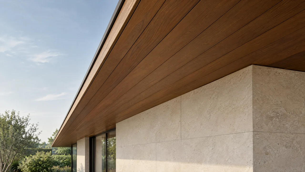
Hardwood soffit boards viewed from below the roof edge.
Architectural context only. Ventilation, fastening and support require the applicable product and project details.One roof edge / Two directions
See what changes when the boards turn
Look up at the same rectangular soffit. Keep the wall and fascia fixed, then compare the board runs.
Wall to fascia
Each illustrated run crosses the projection from wall toward fascia. Review the finished piece length and how many pieces actually fit in usable stock after cuts and end trimming.
Direction study only: board counts, widths and gaps are illustrative. Supports, joints, vents and attachment are not shown. Neither option establishes a buildable assembly.
Compare directions with your measured dimensions ↗Read the building from below
Boards perpendicular to the wall emphasize the projection and produce a repeating rhythm along the eave. Boards parallel to the wall emphasize its length. Carry a sketch around corners rather than choosing direction from one isolated elevation. Window heads, ceiling boards and fascia can create competing lines that are easier to resolve on a drawing.
Follow the support condition
The framing or approved backing determines where a board and its ends can be supported. Changing direction may require a different support arrangement. Long visual runs do not eliminate end joints; the stock length and joint detail still control. Do not let a surface-layout calculator imply that any board can span between any two supports.
Compare a complete cutting assumption
Short cross-eave pieces may share a longer stock board, but saw kerf, end trimming and defects consume length. Long runs may require planned joints and a consistent pattern. Calculate both directions, then let the installer review a cutting schedule using actual available lengths. Retain the discarded option only if it explains a cost or coordination tradeoff.
Work the corner before repeating the pattern
Take a reflected underside drawing to the outside corner and mark the wall line, fascia, vent strip and supports. Draw both board directions through that junction. The question is where each piece ends and what supports it, not simply which set of lines looks cleaner.
A mitered turn, a square-ended border and two independent rectangular zones create different cuts and installation sequences. None is a universal best detail. Compare the visible joint, attachment access, end treatment and the ability to replace one piece. A corner image can express the intent; it cannot establish concealed support.
A cutting example that exposes the missing allowance
Consider a hypothetical 24-foot run with a finished wall-to-fascia piece length of exactly 3 feet. A 12-foot stock board contains exactly 144 inches. Four finished pieces consume all 144 inches before any saw cuts or end trimming. Once cutting consumes material, that four-piece assumption fails. Measure usable stock and state a kerf and trim allowance before treating the geometric estimate as an order.
The layout tool is useful for comparing directions. Its stock count uses your stated kerf and end-trim allowances and is not an optimized cutting schedule. Set both cutting-loss inputs to zero only to compare the geometry-only lower bound. Percentage waste may increase the total purchase, but it does not prove that the specified pieces can be cut from each stock length.
| Decision | Wall-to-fascia runs | Runs parallel to the wall |
|---|---|---|
| Finished piece length | Usually governed by the local projection | Governed by the eave length and planned joints |
| Stock review | Pieces per usable stock board, including cuts | Stock combinations and supported end joints |
| Corner review | How short runs terminate at the return | How the long pattern turns or stops |
| Release check | Actual cut lengths and edge details | Actual joint positions and support details |
Keep the selected direction in the order record
Record the chosen direction by zone, rather than writing “horizontal” on a purchase request. On an underside drawing that word can describe more than one axis. Use “parallel to wall” or “wall to fascia,” and include the drawing reference. If the stock mix changes, check the joint plan before accepting the substitution.
Sources and project evidence
The direction study is a schematic comparison. Cutting examples are original arithmetic using stated stock, kerf and trim assumptions; their board counts are not test data.
What must come from your project
Match the selected direction to the approved supports and end-joint detail. Confirm actual stock lengths and defects before accepting a cut schedule.
Evidence notes checked September 26, 2026. Linked publications support the stated background; they are not an endorsement of this site or an approval of a supplied assembly.
A ROOF-EDGE LAYOUT STUDY
A roof-edge layout study
A nominal 12-foot stock length does not guarantee four finished 3-foot pieces after trimming and saw kerf. Enter kerf and end-trim losses in the layout planner; a real cut list may still require longer stock or fewer pieces per board to resolve defects and supported joints. Leave that difference visible rather than quietly rounding it away.
Your review record
0 of 4 questions reviewed
A checked box records your review. It is not a professional approval.