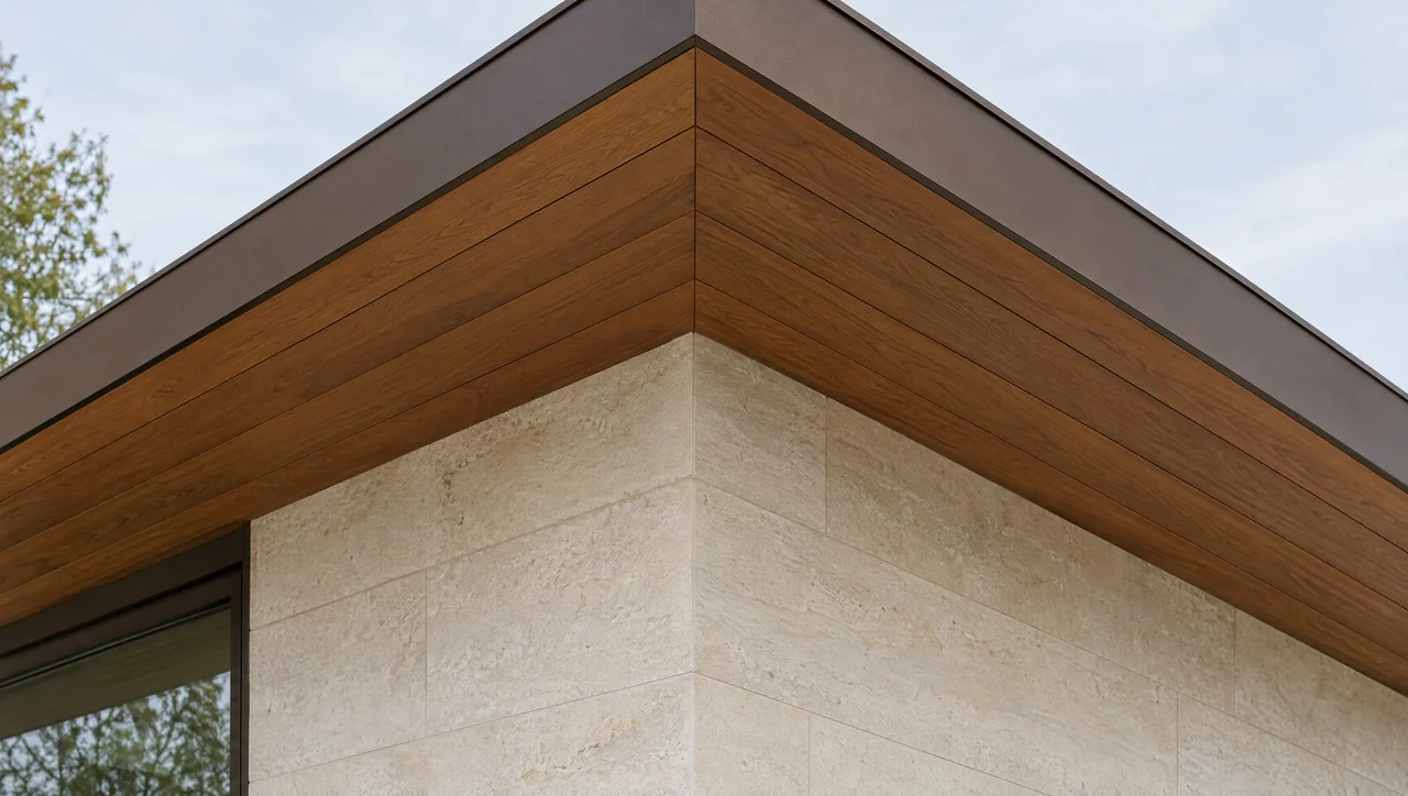
A soffit return at an outside building corner.
Architectural context only. Ventilation, fastening and support require the applicable product and project details.Keep three widths separate
The product name, overall board width and installed covering face answer different questions. A tongue can be included in the overall section but disappear inside the neighboring groove. A shiplap overlap likewise changes coverage. Read the approved profile drawing and ask whether the published coverage already includes an intended reveal.
Avoid the double deduction
If a supplier gives an effective installed module, use that module directly. Do not subtract a tongue or overlap again. If you instead have a verified covering face plus a separate installed gap, add those only as the assembly instructions allow. An aesthetic shadow line is not evidence of the movement allowance that the product needs.
Check the last course
Course rounding can create a narrow strip against the wall or fascia. Before ordering, test whether the layout should be centered, shifted or finished with a different trim detail. A mathematically positive strip may still be impractical to machine or fasten. The tool reports the final face but cannot approve that edge condition.
Three widths can appear on one profile
The overall width, installed coverage and visible face are not always identical. A tongue-and-groove profile includes material concealed in the adjoining board. A shaped edge may create a reveal that changes the visual rhythm. Use the selected profile drawing to identify which dimension belongs in the layout calculation.
A nominal product name does not answer that question. Two boards sold under a similar size description can cover different widths after milling. Before ordering, obtain a sample or a dimensioned drawing that identifies the actual section and the intended installed relationship.
Lay out the narrow direction first
In a long eave, small errors across the soffit depth repeat for the full length. Set out the courses across that depth, including perimeter allowances and any vent strip. Determine the first and last board widths before calculating the long runs.
For an illustrative clear layout width of 30 inches and a profile covering 5 inches per course, six courses fit arithmetically. Add a vent strip or change the actual coverage and the answer changes. Perimeter details can also require a different starting position. The calculation is a layout aid, not permission to omit required clearances.
| Dimension | Use it for | Do not assume it establishes |
|---|---|---|
| Overall milled width | Handling and profile identification | Installed coverage |
| Coverage width | Course count and layout | Ventilation capacity |
| Visible reveal | Appearance and alignment | A required movement allowance |
| Vent opening | The selected ventilation detail | Net free area without product documentation |
Keep a reveal from becoming an accidental vent claim
An open-joint appearance may be intentional, but its gaps must be coordinated with the roof assembly and any screening or backing. Do not count the dark lines in a rendering as intake ventilation. Conversely, a closed tongue-and-groove pattern needs the separately designed ventilation provision where the roof requires one.
Review a sample at the viewing distance and angle expected from the ground. A shallow reveal that looks prominent at bench height may nearly disappear overhead. Grazing sunlight can make small alignment differences more visible. Include the fascia and a vent strip in the sample so the decision concerns the complete eave.
The board-direction guide addresses how the pattern meets corners and changes in depth. Retain the final coverage basis with the quantity schedule. If the supplied profile is substituted, revisit both the order quantity and the course layout before cutting.
Sources and project evidence
Coverage examples use stated fictional dimensions and ordinary course-count arithmetic. A published nominal size is not used as a verified covering face.
What must come from your project
Obtain the supplied profile drawing and its effective installed coverage, including whether a reveal is already included. The mill or product supplier must establish those values.
Evidence notes checked September 26, 2026. Linked publications support the stated background; they are not an endorsement of this site or an approval of a supplied assembly.
A ROOF-EDGE LAYOUT STUDY
A roof-edge layout study
In an arithmetic example, 5.5 inches of covering face plus a 0.125-inch separate gap creates a 5.625-inch repeating module. A product already documented as having a 5.625-inch installed module should be entered as that module with zero additional gap. These values are not a profile specification.
Your review record
0 of 4 questions reviewed
A checked box records your review. It is not a professional approval.