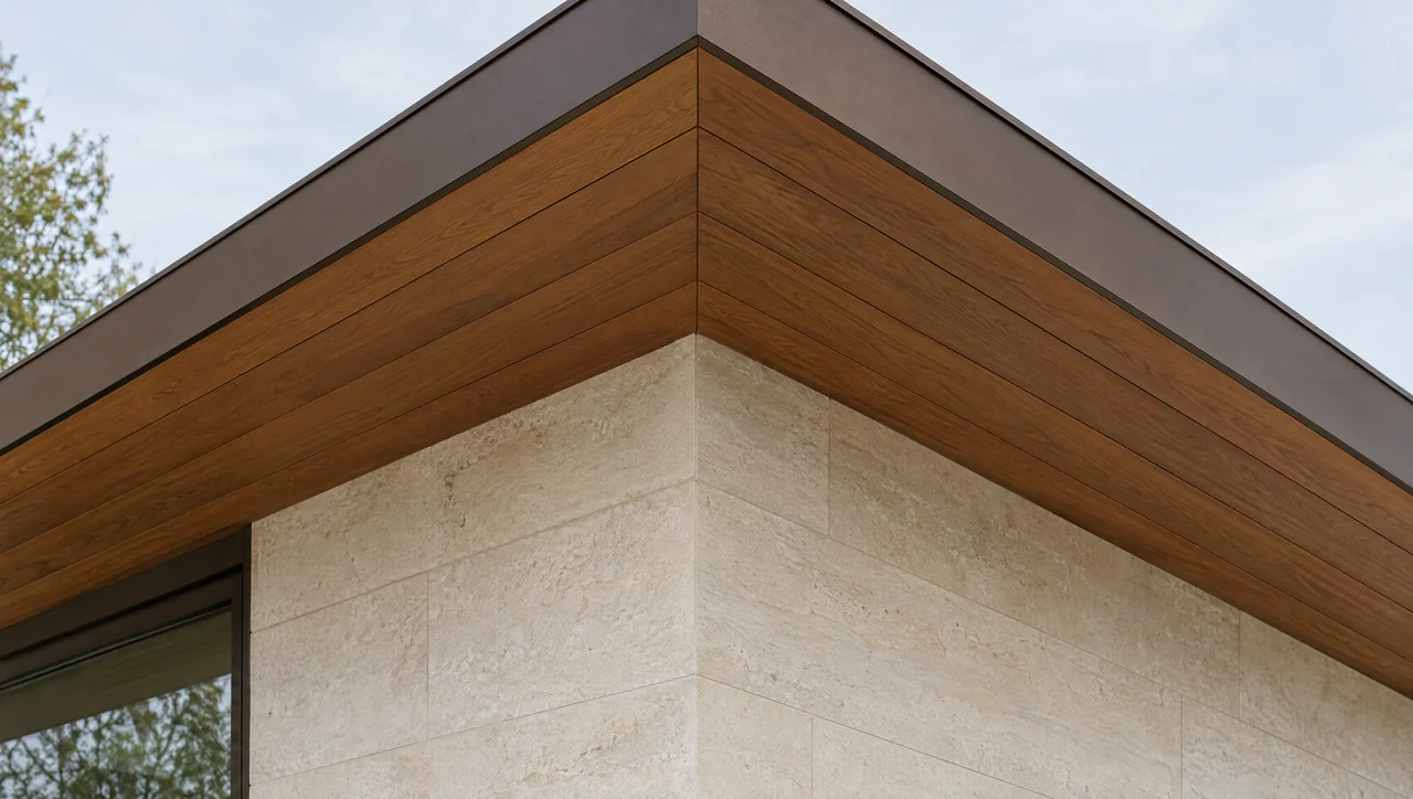
A conceptual soffit corner provides context for defining separate eave and return zones.
Architectural context only; measure from project drawings or the actual surface. The worked zone schedule is fictional.Geometry study / Editable example
Measure the sloping face, not its shadow on the plan
This example is one rectangular band whose long edge slopes in elevation. Width is measured on the finished face, perpendicular to that edge. Do not use roof pitch for a level boxed soffit.
Preparing measurement controls…
Solid line: sloping edge. Dashed: horizontal run and rise. This is a measurement triangle, not a roof or fastening detail.
- Actual sloping length
- 11.180 ft
- Rectangular face area
- 22.361 ft²
- Area using horizontal run instead
- 20.000 ft²
- Area missed by that substitution
- 2.361 ft²
Sloping length = √(horizontal run² + rise²). Face area = sloping length × measured face width. Display values are rounded; this is not a board order or a cut list.
For a taper, curve, compound slope or nonrectangular return, record the actual boundaries separately. The layout planner accepts rectangular surface dimensions once you have established them.
Name the surface you are measuring
Use a short zone identifier on the underside sketch and on every measurement record. A level eave strip, a sloping gable rake and a boxed corner return can look continuous from the ground while having different surface dimensions. Record what each number measures: horizontal projection, slope length or actual finished-face width. A dimension copied from a roof plan is not automatically the length of the wood surface below it.
Use a boundary once
Draw where each zone begins and ends before adding areas. At an outside corner, two rectangular eave strips may overlap on the sketch. Either stop one strip at the other, or isolate the corner as its own polygon and stop both strips there. Do not count the shared patch twice. The choice is a recording convention; the eventual board pattern and corner attachment still need their own detail.
Keep measured area separate from procurement
A face-area total describes the surface. It does not account for effective board coverage, narrow final courses, stock lengths, end trimming, saw kerf or supported joints. Keep these stages visible: measured zones, reviewed board layout, then a stock schedule. Vents and lights can reduce face area while adding cuts and perimeter work. An area deduction is therefore not an automatic reduction in purchased boards.
When a slope correction belongs in the record
Use the measurement triangle only when the long edge of the actual soffit band follows the slope you measured. A level boxed underside below a pitched roof is still level; applying the roof’s slope factor would overstate its length. Conversely, a rake underside that climbs the gable should not be recorded only by its horizontal projection. Write “measured on face” or “derived from run and rise” beside the dimension so another person can reproduce the basis.
For a rectangular sloping band, measure its width across the face, perpendicular to its long edge. The interactive example does not correct a projected width as well as a projected length. If both directions slope, or the band twists, the simple triangle is insufficient. Use the actual geometry from the project drawing or a field measurement record rather than stacking two guessed correction factors.
A zone schedule with an explicit corner boundary
The following schedule is fictional. E-01 ends at the start of the separately drawn corner patch; E-02 starts at the patch’s other boundary. This is why the corner can be added without overlap. The arithmetic assumes rectangular faces and leaves openings undeducted.
| Zone | Recorded geometry | Gross face area | Boundary note |
|---|---|---|---|
| E-01 · level eave | 18 ft × 2 ft | 36 ft² | Stops before C-01 |
| C-01 · corner patch | 2 ft × 2 ft | 4 ft² | Separate patch; neither eave includes it |
| E-02 · return eave | 8 ft × 2 ft | 16 ft² | Begins after C-01 |
| R-01 · sloping rake | 10 ft run; 5 ft rise; 2 ft face width | About 22.361 ft² | Actual slope length about 11.180 ft |
The four gross areas total about 78.361 ft². That total is useful for checking the marked surface extent, not for pooling stock. A corner with diagonal cuts may have a very different yield from an equal-area straight strip. Retain the four zone rows when evaluating direction and available board lengths. Do not divide the combined area by one nominal board width and call the result an order.
Deal with tapers and irregular returns before the board count
Measure the width at both ends of a zone and identify where it changes. For a flat, straight-sided taper with parallel end widths, its geometric area is length times the average of those widths. That relationship does not apply automatically to curved edges, stepped recesses or a surface changing plane. Break those conditions into documented pieces, or retain the measured polygon from the project drawing.
Area alone hides a taper’s installation problem. The final course may narrow along its length, and the wide end can control the stock needed even when the average area is modest. Keep the maximum and minimum face widths in the schedule. The rectangular layout planner should not be fed an average width as if it resolved the taper; use it only for a genuinely rectangular portion or label the comparison as a bounding study.
Record openings without hiding the work around them
- Vent strip: record its occupied band, actual product and interruptions. Keep the published net free area in the ventilation review, separate from wood surface area.
- Light or access panel: mark the cutout and the surrounding trim or backing zone. Use actual product dimensions when available; label provisional openings.
- Column or wall return: identify which surface owns the closure and where the board ends stop.
- Existing obstruction: record what could not be measured and the action needed before a final quantity is released.
Keep a gross area and a separately itemized opening record. If a small cutout is made from a full board, removing its area from a surface total does not mean that fractional board can be omitted from the purchase. A long vent strip can change the number and width of courses on both sides. Review those strips as distinct layout zones instead of subtracting a percentage from the final board count.
The measurement record does not approve the enclosure
PNNL’s wind-washing guidance explains why a soffit intake must work with the air path and insulation boundary behind it. Its guidance on wind-blown rain also shows that roof-edge water entry depends on the assembly, not simply the amount of open vent area. These sources support a separate enclosure review; neither supplies a hardwood fastening schedule or approves the geometric example on this page.
PNNL: Wind Washing addresses air movement and insulation. PNNL: Keeping Wind-Blown Rain Out of Soffits is a September 2011 performance brief with historical code references. Consult current project requirements; do not transplant its illustrated retrofit dimensions into an unrelated hardwood assembly. Sources reviewed September 26, 2026.
Hand off dimensions that someone else can check
Keep the drawing revision, zone IDs, units, measurement date and person responsible together. Attach a marked sketch showing the boundaries; a list of lengths without locations is difficult to reconcile after trim changes. If the field differs from the drawing, retain both values with an explanation rather than silently replacing one.
Next, use coverage and reveals to establish the installed module and board direction to compare cuts and joints. The layout planner handles one rectangular zone at a time. Save each zone’s output with its identifier, then reconcile the stock schedule. The vent area worksheet belongs to a separate ventilation record based on a supplied target and product rating.
Sources and project evidence
The triangle uses the Pythagorean theorem; rectangular area is face length × face width. The fictional schedule is independently reproducible from its stated dimensions.
PNNL · Wind Washing
The relationship between soffit ventilation, baffles and the insulation boundary.
Scope limit: Does not turn a visible decorative gap into a rated vent or certify the concealed air path on a project.
PNNL · Keeping Wind-Blown Rain Out of Soffits (September 2011)
Roof-edge water-entry risks and the importance of the complete soffit/fascia/vent relationship.
Scope limit: A historical illustrated retrofit, not a current code determination or a hardwood soffit specification. Its dimensions must not be transferred to a different assembly without review.
What must come from your project
Retain measured boundaries and drawing revisions. Surface geometry does not establish ventilation, water management, fastening or a stock order.
Evidence notes checked September 26, 2026. Linked publications support the stated background; they are not an endorsement of this site or an approval of a supplied assembly.
A ROOF-EDGE LAYOUT STUDY
A roof-edge layout study
Fictional zone R-01 has a 10 ft horizontal run, a 5 ft rise and a 2 ft face width. Its sloping length is about 11.180 ft and its rectangular face area is about 22.361 ft². Using the horizontal run would give 20 ft². This comparison describes geometry only; it does not specify a roof pitch or a board order.
Your review record
0 of 5 questions reviewed
A checked box records your review. It is not a professional approval.